UML (Unified Modeling Language) is a standard used to create software blueprints.
- There are two main types of UML diagrams:
- Structure diagrams: show the static structure of a system, its components at different levels of abstraction and implementation, and how they are related to each other.
- Behavior diagrams describe the dynamic behavior of a system, representing how objects interact and how the system changes over time.
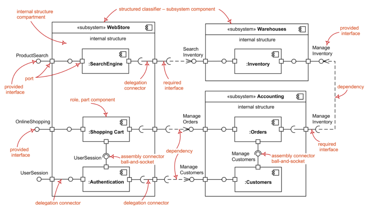
1. Component Diagrams
- Component Diagram describes the static implementation view of a system.
- It shows components, their interfaces, and relationships.
- It is used in Component-Based Development (CBD) and SOA.
- Components are reusable, replaceable, and independently deployable.
- Use this when:
- Designing system architecture
- Breaking system into modules/components
- Showing how components interact
- …
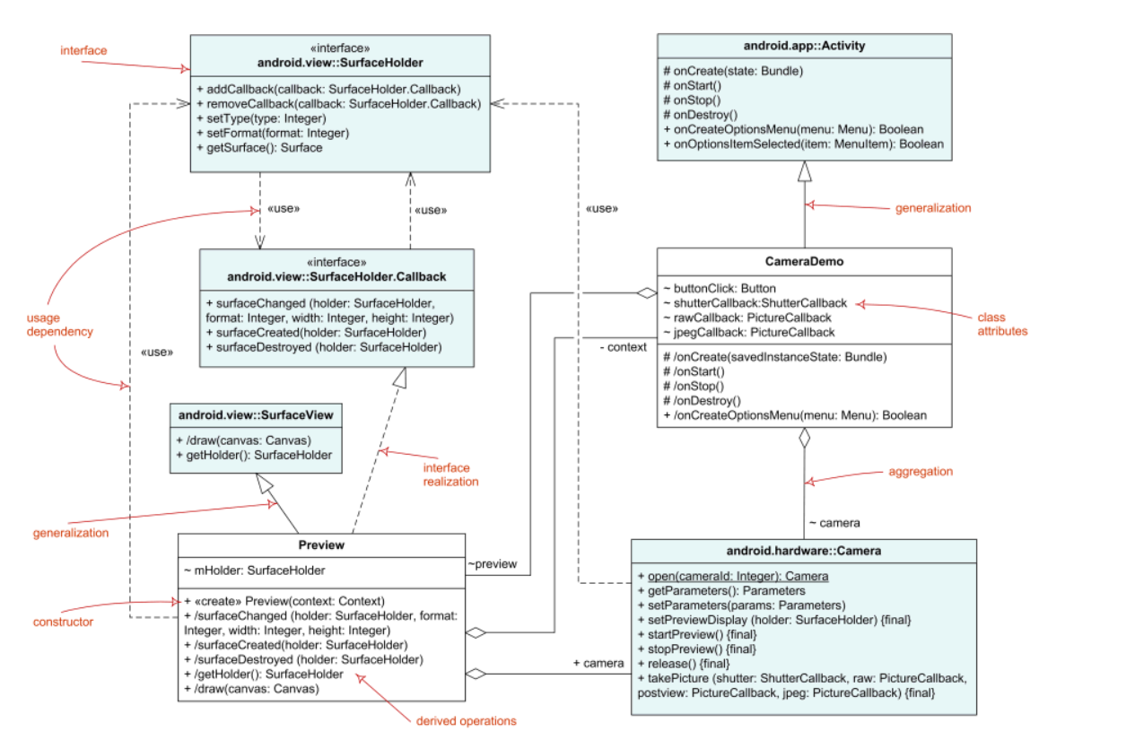
2. Class Diagrams
- Class Diagram is UML structure diagram which shows structures of the designed system at the level of classes and interfaces, shows their features, constraints and relationship (associations, generalizations, dependencies,..)
- Use this when:
- Designing classes and their structure,include attributes and methods before coding
- Showing relationships between classes
- Detailing components at a deeper level
- …
1.1. Classifier Relationship
- Association
- Directed Association
- Reflexive Association
- Multiplicity
- Aggregation
- Composition
- Nested Classifier
- Dependency
1.2. Roles
- Abstract Class: The name of an abstract class, method is shown in italics. An abstract classifier can also be shown using the keyword
{abstract}or<<abstract>>after or below the name. - Static: Class (i.e. static) methods and fields are indicated by underlining
- Constant: (i.e. final) fields are indicated via naming convention: constants should be in ALL_CAPS
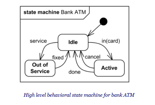
3. State Machine Diagrams
-
State machine diagram is a behavior diagram which shows discrete behavior of a part of designed system through finite state transitions. State machine diagrams can also be used to express the usage protocol of part of a system.
-
Use this when object behavior changes based on state.
4. Activity Diagrams
-
Activity Diagram is a UML behavior diagram that shows the flow of control or object flow, focusing on sequence and conditions.
-
Actions can be triggered by completion of other actions, availability of data, or external events.
-
Use this when:
- Modeling workflow or business processes
- Describing step-by-step logic (like algorithms)
- Showing conditions, loops, and parallel flows
- Explaining how different parts of a system interact over time
-
Example: Library System – Borrow Book Flow
- User searches for a book
- System checks availability
- If available -> proceed to borrow
- If not -> show unavailable message
- User confirms borrow
- System creates loan record
- Book status updated to “Borrowed”
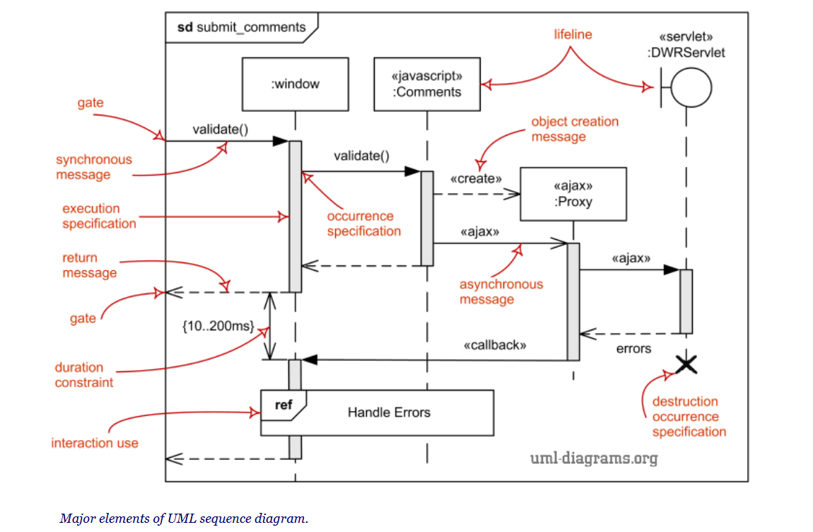
5. Sequence Diagram
-
Sequence Diagram is an interaction diagram that shows how objects communicate through messages over time.
-
It focuses on the order of messages between lifelines.
-
Use this when:
- Modeling interactions between components or objects
- Showing step-by-step message flow for a use case
- Designing APIs or method calls between classes
- …
6. Example: Library System – UML Usage by Phase
6.1. Analysis Phase
- Activity Diagram
- Purpose: model workflows
- Example: Borrow Book process
- Search book -> Check availability
- If available -> Borrow
- Else -> Show unavailable
- …
6.2. High-level Design (Architecture)
- Component Diagram
- Purpose: define system structure
- Example components:
- User Interface
- Book Management
- User Management
- Borrow/Return Service
- Database
6.3. Detailed Design
-
Class Diagram
- Purpose: design internal structure of components
- Example:
- Book (title, author, status)
- User (userId, name)
- Loan (borrowDate, returnDate)
- BorrowService (borrowBook(), returnBook())
-
Sequence Diagram
- Purpose: show interaction between objects
- Example: Borrow Book
- User -> UI: request borrow book
- UI -> BorrowService: borrowBook()
- BorrowService -> Book: checkAvailability()
- BorrowService -> Loan: createLoan()
- BorrowService -> Book: updateStatus(“Borrowed”)
- UI -> User: confirm success
-
State Machine Diagram
- Purpose: model object states
- Example: Book states
- Available -> Borrowed -> Returned